Notes on DBSV8 Bosch Fuel Injection Systems
by Jonathan Hill
ANDY CHAPMAN wrote a superb article in the AMOC Summer 1984 Quarterly Vol 21 No 88, on the DBSV8 fuel injection system. This should be begged, borrowed or stolen, but preferably read, by anyone aspiring to tinker with this system . The following is not intended to modify anything he stated in the article, but rather to give some practical advice on how to follow his instructions. The checks that Andy suggests in his article are fairly straight forward to carry out with the exception of setting the levers to the tolerances he advises which is a very tedious job.
There is a simple modification to the standard system which I will describe later which makes the setting of the levers much simpler, but first I will describe how to set the levers using the standard set up. There must be many ways to do this but the method discussed is one I have used with success.
The first job is to cut and file two pieces of rod to 193.3mm and 187.2mm respectively. In my case old motorcycle wheel spokes were used but any suitable light rigid rod will do. To file the rods up to exactly the dimensions suggested is obviously a tall order but get them as close as you can. I had several attempts before I was satisfied with the result. Next loosen the pinch bolt holding the lever which operates the injection pump which is situated on the middle of the cross shaft. Halfway up this lever is a 2B.A nut and bolt which secures a small cast alloy lever to the main lever which operates the left hand half of the cross shaft. Loosen the 2B.A bolt. Before proceeding any further check that the three needle roller bearings on the cross shaft are correctly located. The two outside bearings should fit snugly in the channel section at the back of the air boxes and not be free to pivot about the 1/4" set screw. In a similar way the centre bearing should be unable to swivel about its set screw - a few moments examination will reveal the correct location. Now take the 187.2mm rod and adjust the ball joints on the rod operating the injection pump so that the distances centre to centre are as close as possible to the length of the rod. Do not tighten up fully as you may have to make minor adjustments to this linkage later on.
Using the 193.3mm rod carry out the same exercise for the outside rods. This is much more difficult as you cannot see the end of the linkage without using a mirror. Again get them as close as you can as diligence at this stage will obviate a lot of adjustment later on. I am assuming the throttles have been svnchronised and that when on their stops the pointers on the sides of the airboxes have been bent so that they bisect exactly the '0' on the scale. Now tighten the pinch bolt of the central lever and the 2B.A bolt. If you are very lucky the two outside pointers will still be reading exactly '0' and so will the injection pump pointer. If so check the readings of the throttles and the injection pump by taking readings at throttle settings of 2.5, 5.0, 7.5, 10.0, 15, 20, and so on. Write down the results you obtain, If the settings are now exactly to Andy's requirements you can tighten up and recheck and give yourself a drink, but if they are not proceed as follows. Loosen off the 2B. A. bolt in the centre and concentrate on the right-hand side throttles and the relation with the pump.
First make sure that both the pump and the right-hand side throttles are registering '0' when at rest. Again run the check with the throttles at 2.5, 5.0, etc., and write down the results. Your results will indicate which way the linkages have to be moved. For instance if the pump is going ‘too fast' then either the pump link is too long or the throttle linkage is too short. You will only need to move the linkages very small amounts to bring about a large change in the read-outs. You will need patience, but you can eventually get the readings correct. Having got the right-hand throttles correct in relation to the pump and here near enough is not good enough, you must get them correct, you now need to adjust the left-hand throttles to match the right-hand set. Tighten up the 2B.A bolt on the central lever and check after you have done this
that both throttles are reading '0'. Now check the two sets of throttles to see if they are reading the same at 2, 5, 10 etc. You may find that the left-hand throttles are a degree or so in front of the right-hand set. If so you need to release the 2B.A bolt on the central lever and move the setting in the required direction to get them into phase. You may find, however, that although the two sets of throttles are starting at '0' the left-hand set are advancing too fast or too slow. If too fast the left-hand throttle linkage is too long and you will need to shorten it.
Only move it by very small amounts, say ¼ turn at a time, but having moved it you will, of course, upset your '0' setting so back again to the 2B.A bolt on the central lever to get both sets to '0' at rest. Try again remembering that the right-hand throttles are spot on and all you are trying to achieve is to get the left-hand set to match them accurately. This is all very tedious because each time you make a small adjustment to the linkage length you have to go back to this 2B.A bolt on the central lever. As this is situated right in the centre of the car amidst many pipes and obstructions and on the standard set-up it needs two spanners to tighten the bolt this task does require great patience. Persevere and you can get the 'book' settings but it does take time.
Now to the simple modification. This relies upon the fact that you lock up the centre levers and make all adjustments on the ends of the cross shafts. Remove the cross shafts from the car and detach the small cast alloy levers from each end by driving out the 'roll pin securing them to the shaft. Make up two new levers (See diagram 1) so that they can be secured to the ends of the cross shaft by tightening a single Allen Cap Head Screw. The setting of the levers is now much simpler. Leaving the two new levers free to rotate round the ends of the cross shaft do up the centre levers tight. Adjust the pump to centre lever link as before to 187.2mm and the outer linkages to 193.3mm. Check that all pointers read '0' when at rest and then tighten the new lever on one set of throttles. Any adjustments you now make to the linkages to make the readings match the book will only require you to release the end lever and try again. This action only requires the use of an Allen key in one hand whilst the other is persuading the system in the required direction. This greatly simplifies obtaining the 'book' settings although you will still need to make tiny adjustments to the three linkages to get there. The modification is well worth making as quite often the tiny roll pin in the original cast alloy lever works loose and upsets your carefully won settings.

Making the Levers
If you are tempted to knock up these levers from a bit of scrap alloy lying around in the workshop, a word of caution. Choose a bit of high strength alloy 3/8ths inch thick as the 14" UNC thread will need to be able to withstand repeated tightening as you do your adjustments. The hole centres seem to me to be 1" apart but it is safer to use the old lever as a pattern. The larger hole is 0.463" on my car, but check on your own car before making the hole. In my experience this needs to be reamed so that it accurately fits the end of the cross shaft.
Failure to do this will mean that all will be fine when you are tootling around setting the timing at TDC at idle the full advance the idle, but after a really hard caning the underbonnet gets so hot the alloy levers expand and can slip round the shaft.
Setting the Idle
Andy Chapman gives very precise and simple instructions for this operation. To check idle mixture detach the pump linkage with engine idling at 850 rpm and move pump from 0° to about 3° If revs increase pump is weak. If the revs fall off pump is rich. You will have to carry out this operation with the engine and everything you touch very hot so it is a good idea to ensure that the rearmost ball-joint on the pump linkage can easily be detached from the central lever. Some come off more easily than others so choose a ball joint that detaches easily for this spot.
Rack Adjustment.
Andy Chapman suggests that the amateur does not move the rack adjustment by more than two clicks. He says that this is a very coarse adjustment and affects the complete range and is not recommended to be touched other than by an 'experienced Mechanic'. I am very reluctant to disagree with Andy on this point but the pumps that have been returned to me by the expert reconditioners have always been very rich on the rack adjustment. Mine have required about 10-15 clicks weaker to get the ideal state of about 14 mpg, sparking plugs brown on the outside and clean porcelain on the centre and nice light grey in the tail pipes. I was very reluctant to tamper with the rack until Dave Jack of Aston Engineering encouraged me to do so.
Under his instructions, over the telephone, my car now gives 14 mpg, no surge and snatch when tootling along on a light throttle, grey in the tail pipes and a breathtaking performance everywhere else. So whilst great caution is advised here I think it is probably easy for the amateur to detect weakness in the 1000-3500 rpm range as the car just does not perform really crisply. Over 3500 rpm it is probably much more difficult to detect if the engine is running weak so you should probably have a specialist at your elbow. Andy Chapman is obviously one and Dave Jack another, and there must be more I have not come across so do not meddle with the rack unless you are very sure of yourself or have a specialist on call.
If, despite my warnings, you decide to tiddle you will need two tools to adjust the rack. The first is a 5mm Allen key to remove the Allen Cap Head screw at the rear of the pump which uncovers the rack adjusting screw. You will then need a special short screwdriver with a 2 1/2 " shank culminating in a 1/8" bit with a handle about 1/4" long. To adjust the rack remove the 5mm ACH screw, insert the special screwdriver and engage the slot in the screw. To move the rack press against the spring pressure you encounter until the screw will come up against a stop and move in the required direction, clockwise to weaken-anticlockwise to richen. Move it a couple of clicks between trials until you get the required result. Do not leave out the ACH screw between adjustments as oil will pour out through the hole uncovered.
The Distributor
Andy Chapman's requirement is for the ignition timing to be TDC at idle and no more than 30° at full advance. I have no experience of the twin contact breaker system originallv fitted to these cars so the following refers only to the Lucas 'Opus' system fitted to later cars. The 'Opus' system works as follows. A vacuum capsule provides 10° of retard when the throttles are closed. A mechanical system provides 20° of advance as engine speed is increased to give maximum advance at about 3000 rpm.
So in the ideal situation the timing is set so that at idle the timing occurs at TDC. As soon as the throttles are cracked open the vacuum retard ceases to operate and the engine is running at 10° of advance. From 600 rpm onwards the mechanical advance takes over progressively advancing the timing to 30° at 3000 rpm.
On a brand new 'Opus' distributor Lucas quote a range of 8-12° on the vacuum retard and 18-22° on the mechanical advance. So even on a new unit the total advance could be between 26° and 34°. On a worn unit these tolerances could be greatly exceeded so that even though you can set the timing accurately to TDC at idle the fully advanced figure could be 35° or so. In my experience the engine is much happier at 30° total advance so it is important to modify the distributor to give the correct figure.
The first task is to set the idle to TDC using a timing light. The marks on the crankshaft shock absorber needs to be marked with paint at TDC and 30° advance before carrying out this test. Then rev. the engine to 3000 rpm and judge the full advance figure. I say judge it because the light is likely to be darting about round the painted mark. This is because the distributor is driven by two sets of chains from the crankshaft end and then by a four or five inch extension of the 'A' bank exhaust camshaft. Even on a rebuilt engine with new chains and correctly set tensioners the light will dance about. A worn distributor will not help matters. Assuming all is in good order it should be possible to make an estimate of how far in front or behind the ignition timing is. If the light is near enough to 30° at 3000 rpm then leave well alone. If not the distributor will have to be dismantled to adjust the stops inside to give the correct advance. First with the car in 3rd or 4th gear and handbrake on move it until No.1 cylinder on .A' bank is at TDC on the firing stroke. When this position is reached the pointer on the crankcase will be pointing somewhere near the TDC mark AND the rotor arm in the distributor will be pointing to the contact where No. 1 HT lead exits from the distributor cap. Note the position of the rotor so that it is replaced in the same position when the distributor is refitted The distributor should now be dismantled.
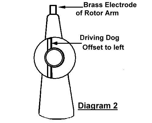
Points to note. A set of circlip pliers should be used to remove the circlip from the top of the timing rotor as if you lose or damage this you may have difficulty finding another one. Note the position of the various pieces as you dismantle and note that the base plate below the pick-up cannot be removed without first removing the vacuum capsule. When you have uncovered the mechanical advance unit clamp the lower stem of the distributor gently in the soft jaws of the vice. The task now is to limit the movement on the mechanical advance so that it moves 10° (equals 20° on the engine). Twist a piece of light rigid wire around the top part of the mechanical advance so that the end of this pointer runs around the top circumference of the distributor body. Make two pencil marks 0.322" apart round the circumference of the distributor body and whilst holding the lower part of the mechanical advance rotate the top section and check it travels no more: (or less likely) or less than 0.32". You will be able to see that at full advance the movement of the top plate to which the inner ends of the springs are attached is limited by a lug which abuts against one of the posts to which the outer ends of the springs are attached. If you have less than 0.32" movement small amounts have to be ground at the end of this lug to make the advance correct. It is much more likely, however, that manufacturing tolerances and wear on the end of the lug will mean there is too much movement. In this case put a blob of weld on the end of the lug and grind it back to give the correct movement. To do this the upper part of the mechanical advance mechanism will have to be removed from the lower half. Remove the felt in the recess below the rotor arm and remove the screw revealed. The top part of the mechanism can now be removed from the lower half by very carefully easing the outer ends of the springs off the posts and pulling the top half upwards. In the same way mark the springs so that they go back in the same places and most importantly make sure you reassemble the lug so that it abuts against the same post as before. Failure to observe this will mean that the distributor is put back on the car 180° out of phase. To check you have reassembled correctly hold the distributor horizontally with the lower driving dog pointing towards you. The offset on this driving dog should be on the left when the brass electrode on the rotor is pointing vertically upwards. (See diagram 2). Whilst you have the distributor dismantled this far it is a good idea to knock out the pin holding the driving dog and withdraw the shaft from the body. These units seem to last for ages but sometimes a little condensation gets in and it is as well to clean up the shaft and make sure there is plenty of lubrication on reassembling. Any end float on this shaft will contribute to timing inaccuracies. Lucas do not quote a figure but 4 thou would seem to be about right allowing for the differential expansion of shaft and body.
You will note that no method for correcting the vacuum capsule has been given. This is because I cannot see a simple way to do this and so would arrange matters so that the TOTAL advance was no more than 30° and not worry unduly if the vacuum advance was not spot on 10°
Having made all these adjustments to your satisfaction they should be checked on the car. The offset dog makes it easy to replace the unit in the same position as before and you should then check that with of 3000 rpm is very near to 30°. The method I have described seems very crude, but it works well in practice and certainly my car feels much happier at 30° full advance than the figure when I bought the car.
Performance
Aurhentic road tests of the DBSV8 compared to the Vantage show that the DBSV8 will pull away from a Vantage up to 100mph. Possibly the more slippery shape of the Vantage starts to win over 100mph. So if it is performance you are after the DBSV8 is worth thinking about because it will hold its own in the companv of all but the most exotic supercars.