DBSV8 Workshop


Andy Chapman gives advice on tuning the FUEL INJECTION

These cars have built up a reputation for giving trouble because some people in the Motor Trade say they are ‘bad news’ My findings are different with these cars, but they do need more time spending on the initial setting up over a carburettor V8. Once they have been set up properly they are a very reliable unit. I hope the V8 owner agrees after reading this. Listing some of my experiences with this system will no doubt help my business competitors, but hopefully it will also help the owner of the V8 fuel injection cars which is the main consideration and also perhaps improve the fuel injection ‘image’.

Figure 1 shows the diagrammatic layout of the fuel injection system. Most of the settings and adjustments to the linkages are done on a test bench and should be left alone. I shall refer to Figure 1 below later in these notes.


Fig.1 Diagrammatic Layout of the BOSCH Fuel Injection system 

1. Main Tank
2. Fuel Pump
3. Surge Tank
4. Petrol Filter
5. Fuel Gallery
6. Control Rack
7. Control Sleeve
8. Plunger
9. Cam
10. Camshaft
11.Bearing
12. 3D Cam
13. Centrifugal Governor
14. Swivel Lever
15. Control Lever
16. Throttle Cross Shaft Lever
17. Control Valve
18. Thermostat - Coolant Temperature Correction
19. Altitude/Atmospheric Compensator
20.Injector
21. Pressure Relief Valve
22. Injector Pump body
23. Link
24. Correction Lever
25. Rack Reversing Lever
26.Bell Crank Lever and Follower


Tappets & Valve timing

The V8 fuel injection engine has a habit of ‘choking’ itself on warm up if the tappets have closed up and the valve timing has altered due to wear, i.e. if every other setting is correct. Most carburettor engines do not show up faults when the tappets and valve timing are not standard. Therefore it is quite important to get these settings correct so that a fuel injection engine will ‘‘breathe correctly”. These are as follows:

Valve timing inlet open .060” @ TDC. Tappet .009” to .010”

Valve timing exhaust open .050 at TDC. Tappet .010”io .011”

Engines which have covered 40,000 miles since any top end work ought to be looked at. Tappets close up, timing chains wear and if the tappets close too much then the back of the cams become damaged. This is my advice, especially if the car has been driven hard.


Distributors


Distributors

Faults: — ‘popping’ back through the air filters and some rough running. Twin contact distributors are a problem but OPUS ignition has overcome some of the problems. The base plates develop up and down play at point A, figure 2, and sideways play at point C. The rev-counter needle usually jumps when this fault is apparent with the engine idling. Remedial work can remove play at A -& C, but the important point is the plate must swivel freely with no play i.e. vacuum capsule or servo unit must be able to operate correctly. Replacement base plates, Lucas part numbers: Top plate number 54422584 and bottom plate number 54422617.

Thermostatic Fuel Pump

(number 18 figure 1)

Faulty operation will cause enrichment. This controls the mixture correction for different engine- temperatures and the additional air needed for the warming up period. The test to ensure correct operation is to remove ‘A’ cylinder bank air filter. Start engine from cold and at around 70°C, the air should stop or almost stop, being drawn through a hole at the rear of the filter base, Should the air continue to be drawn through the pipe, then the injection pump will not weaken off the mixture as designed. -
To test the fuel injection thermostat, remove and measure the distance as shown in figure 3. Warm up to 70°C and the rod should have moved nut a minimum of 3.5 mm. If all is correct and still draws in air, then fit a 2BA washer in the plunger which should take care of this.


Vacuum servo or capsule

Popping back on initial acceleration is a symptom of the vacuum retard being ineffective. The capsule must hold vacuum
and retard the ignition at a minimum 100 in static condition. To test this: engine at running temperature, idling, and ignition timing TDC at 950 r.p.m. and remove the vacuum pipe from the capsule. The engine will build up to 1200 r.p.m. and normally the ignition will increase to 120 to 15° BTDC. Anything less will cause this popping back and as in the early days the fuel injection was blamed until experience proved otherwise. Whilst on ignition the maximum advance is 30° at 3000 r.p.m., engine hot.

Vacuum Switch.
This switch must not hold the throttles open at idle: therefore the switch- should compress another .030” with the throttle shut
Engine Thermostat Fuel injection Engine The engine thermostat should open at
88°C; this is necessary to ensure that number 18 (figure I) carries out its operation correctly.


Injection Pump — Oil Level 

Fault — high level causes richness. The level in the pump increases at varying rates depending on the wear in the pump. - Should the level in the pump come up to the top of the threads in figure 4, then the engine will run rich as the oil interferes with the governor operation (number 13, figure 1).
-The oil will get diluted with petrol and should be changed a’. regular intervals. It is best to maintain the level at ½” below the mark on the dipstick. I have known pumps to need checking at 2000 miles because of the wear and I am sure that now there are a lot of worn pumps, so regular checking will be needed.


Providing the relationship between the throttles and injection pump are adhered to in the table below then that is the objective.


Injection Pump               Throttles                 Tolerance

0                                             0

4.6                                        2.5

8.8                                        5.0

12.7                                       7.5                             ±0°

16.3                                       10

23.1                                       15

29.3                                       20                             ±½°

40.5                                       30

50.5                                       40                             ±1°

59.4                                       50

67.4                                        60

74.4                                       70                             ±2°

81                                          80.7

84                                             Considered Maximum Throttle


If you want economy from this system then throttles must be accurate from 0° 15° on throttle and as close as can be

maintained after that, the closer the better.


Throttle Butterflies 

These must shut into their housing perfectly so that all the idle speed control comes from the valve in Figure 6. Sticking open, throttles must be overcome.
The pull off springs in Figure 7 tend to force the butterflies against the manifold at point B. I suggest for the perfectionist that they aim at getting the springs to ‘pull off’ in the line of the dots. This will reduce the tendency for ‘sticking’ butterflies.


Fuel Pump (number 2 — Figure 1)


 This pump runs at l0tbs/sq. in.
pressure. Any drop in pressure of ½ lb/sq. in. will cause weakening-off of the mixture. A faulty pump is uncommon but by now there must be a lot of nylon filters on the input side of the pump in need of cleaning out. This filter, if blocked, will cause a drop in pressure as will filter Number 4 if not changed every 5000 miles.
Also Number 21, the relief valve which maintains the pressure in the system. I have only come across dirt under this valve causing a loss in pressure on one occasion. Testing the pressure:— fix pressure gauge to feed to the cold start valve, run engine, note pressure, blip throttle to around 4000 r.p.m. and only minor fluctuations should be observed. If fluctuation over ½ p.s.i. occurs then this will cause a weakening-off and popping back through the air box. For ‘Mr. Average’, clean the pump filter and replace paper filter and do not get too worried about this section.


Cold Start — Thermostop 

If this is a problem it can be electrical, but, one fault that has occurred about once a year, is the thermostop ‘plays up’ and either non-functions or floods the engine.
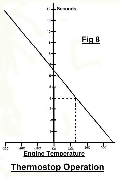
To test:—remove the outlet pipe from the cold start solenoid and crank engine with the coil lead off. Time the duration of petrol from solenoid, Figure 8 shows duration of cold start spray, e.g. engine temperature approximately 13°C. Time of spray during cranking on the starter is 4 seconds. A little leeway is acceptable in the timing.

Sparking Plugs 

BP6ES NGK plugs have been found a lot more flexible in service. They have not fouled up so quickly especially when moving the cars around in the workshop when the injection system is automatically on a rich setting.
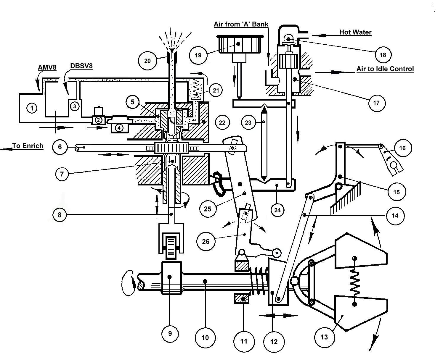
Injection — (Control Rack Number 6 — Figure 1)

Once we did have a control ‘sticking’ and it was freed off without dismantling; I only mention this in passing.
Throttle Cross shaft

Where the shaft comes out of the bulkhead from the throttle pedal there is a small roll pin which is prone to break. I have normally drilled out to ¼ and fitted a larger pin

Road Tests  
Now having set all the above, which must take time, we come next to some of the running operations; What we are aiming at is an engine which should do about 14 mpg., sparking plugs looking browny-coloured ‘soot’ on the outside and clean porcelain on the centre. The exhaust, looking a nice light grey and the engine driving on light throttle without ‘snatching’. If an injection pump is set correctly and has not been tampered with, then the only adjustment necessary after all the previous work mentioned is the idling mixture.


Idle Mixture

With the engine at correct running temperature this mixture can be checked and reset without a C.O. meter. By disconnecting the rod, move the-fuel injection lever (Number 15 — Figure 1) slowly over from O° to 3°. If the engine revs increase the pump is weak, if the revs fall off, it is too rich, and if the revs remain even over this period, the mixture is about right. To set the mixture it is ideal to weaken the mixture by the screw in Figure 9 below, until when moving the lever a slight increase in revs is detected before leveling out. Then richen by two clicks on the screw, which should give the correct mixture. DO NOT ADJUST WITH THE ENGINE RUNNING — clockwise richen, anti-clockwise weaken.


To check the mixture, blip the throttle up to 2000 r.p.m. and if the revs drop to around 850-900 and recover to 950 r.p.m. then the mixture is good. If you have a C.O. meter 5% is about right, and some engines prefer 5½ %. Each time an adjustment is made run the car over ¾ of a mile and recheck. This is to ensure that the under- bonnet temperature is correct.


At this point most cars should be running satisfactorily, BUT, there may be many vehicles at this point which have been tampered with in order to overcome a fault. The favourite one is, if an engine has run rich either because over filled with oil or the fuel injection thermostat is not working properly, or incorrect throttle linkages, the rack adjustment has been tampered with Figure 9. Now this adjustment is a very coarse adjustment and two clicks each way is the maximum’ one should go. This adjustment affects the complete range and is not recommended to be touched other than by an experienced mechanic’ with a C.O. meter. This screw is anticlockwise to richen and clockwise to weaken.
In the early days of VS fuel injection engines after carrying out all the tuning checks as listed, we still had popping-back through the air box on acceleration. By richening the rack one click, then readjusting the idle mixture, we overcame the problem.
Figure 10 shows the end of ZZ in Figure 9. The centre screw we have discussed, but the other four screws are for adjusting only on a test rig. - If before tuning the engine it had been running very rich for a long period and returning something like 8 mpg., the car should be driven over 300 miles and rechecked again. In my experience after 300 miles the car tends to weaken off and needs a final setting on the mixture. The faults tend to show up in the warm-up period with popping back through the air box, but adjustment to the idle mixture is all that is necessary.


Hot Starting 

Hot starting to a proud owner can be an embarrassment with a lot of on-lookers. The main problem is that with the engine switched off on a hot day the heat soak boils the petrol in the galleries and injector pipes. The technique is to switch on the pump and leave it to run for 20 seconds. Sometimes you can hear the air bubbles going back into the tank behind you. This helps cool the injection pump and removes air from the gallery (Number 5 — Figure 1), Give the engine full throttle and crank until the engine fires up and ‘back off’ immediately; as some of you know this can be a few seconds. If the engine is still a poor starter then wire in a switch similar to an electrical aerial switch
and put the wire to the cold start solenoid.
On a hot day switch on the ignition, press the cold start solenoid switch for two seconds and the engine should start with little trouble. In this article I hope I have covered about 95% of the problems. Plug leads should have a resistance of 15,000 ohms per meter in length; anything over that and we replace. On compression testing I have found that these can vary from engine to engine. If they are even and around 130 p.s.i. or 150 psi. then the engine is satisfactory; although
130 seems low, many fuel injection engines are around this figure. Always check compressions with a warm engine. A variation of 25 p.s.i, shows there is a fault, although when driving the vehicle it appears satisfactory. Injectors and the atmosphere - adjusting unit (Number 19— Figure 1) have not been found troublesome. Injection pump timing is not critical to one tooth either way, but, 180° out can cause low speed running problems. - Some early V8 fuel injection Astons which have been well driven and looked after go extremely quickly. Perhaps not as quick as the Vantage, but the performance is still outstanding!

Fuel Injection advice reprinted with kind permission from Andy Chapman A.A.E. Mech Eng M.I.M.I. and the Aston Martin Owners Club